 Our discussion on resistors is certainly not complete and I would like to touch on it again later when I expose you to SMD's (surface mounted devices). However I promised to discuss capacitors but I'd like to keep it short as I would firstly like to cover electronics in general before we continue with electronic components.
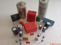
Capacitors or caps as they are more commonly known by the initiated, comes in various shapes and sizes, forms and ratings, meaning it can be shaped like anything from a matchstick's head to that of a bullet's casing. They can be as small as a pin's head to as large as a cake tin and shaped like that as well. They can be rated to withstand as little as 1.5Volts across their terminals to several hundred volts and when the rated voltage is exceeded or the polarity reversed, they may explode. Yes, you read right, capacitors do explode and they make a really loud bang and the smell that accompanies it takes some getting used to. However, some capacitors are polarity conscious, then there some that are not. Reversing the polarity on a capacitor willfully is not a good idea, so always make certain you insert a cap into a PCB correctly. Capacitance which is the property of caps is measured in Farads. A one farad capacitor could be as large as a car coil or a litre bottle but all caps are tiny compared to this, so we use micro farads, (millionths of farads) instead. The symbol for micro farads is μF. (the character that looks like a U is the greek character mu) Caps are produced from various materials like cardboard and foil paper placed in aluminum canisters along with electrolyte, some are ceramic encapsulated. Other are just two metal electrodes separated by glass and air. You will not be required to make caps, but rather buy them from the thousands of electronic component dealers world wide.
Caps have the ability to pass AC (alternating currents) and block DC (direct current) and are used extensively in power supplies where the charge and discharge rates are key to smooth out any interference from the input power. Essentially, caps can be describes as to wires (called electrodes) physically isolated, with a substance in between them, which is capable of storing the potential difference developed between the two electrodes. Restated caps can hold a charge if subjected to it, sometimes for a few days but it will decay over time. However, should you touch both electrodes of a cap that is charged by mains voltage, with your bare hands, it can really get your attention, it will give you a really mean electric shock. So now that I scared away the timid, let me go to the electronics discussion, but will return to caps later.
A TV aerial made of aluminum may not seem like an electronic device, but it does contain a tiny PCB (printed circuit board) which supports two or three ceramic caps along with a coil or two to which the coaxial cable gets to be attached. This aerial's shape and size has been mathematically calculated based on harmonics of the signal its suppose to receive, and along with the caps, form a tuned circuit targeted for a specific frequency range, Hence you get VHF aerials, UHF aerials, whip aerials, dipole aerials etc etc...
A heatsink has no electrical properties and its normally just a piece of aluminum attached to or to which some electronic component is attached in order to keep it cool. A microprocessor's heatsink for example would even have a fan fitted onto of the aluminium to stop the microprocessor from going into thermal runaway. Aluminum has a good heat dissipation factor hence it is predominantly used in electronics even though at times copper is also used as heatsinks.
A transformer is normally two coils of wire isolated from one another but coexisting in close proximity on the same core which is often made of ferrite but also mild steel plates. These plates are composed of E shaped plates and I shaped plates oppositely interleaved to created numerous figure 8s, then packed on top of one another. The two holes in the figure 8 is where these coils of wire live. The core of the transformer is were eddy currents rise and fall to cause magnetism which roughly describes transformer action.
A speaker is like a transformer except that the current driving its coil is powered by an amplifier rather than mains electricity, which creates magnetism to drive its cone which intern displaces air. The moving air interacts with our eardrums which we interpret as sound.
A microphone is the inverse of the speaker and roughly uses the same technology whereby our voices moves its diaphragm, which moves across a magnet to produce a current in its coil destined as input to an amplifier. Speakers and microphones are essentially called transducers but we will have to return to that topic at a later date.
A relay is essentially a remote switch which can have numerous contacts to switch heavier loads than what the relay switch can handle. Relays come in various sizes and various current ratings. Relays in essence are mechanical contacts controlled by an electromagnetic field, created by a coil which moves a mechanical lever or plunger which is responsible for the electrical switching.
I will continue with this discussion next blog. If you find this blog interesting please recommend it to others by clicking on the g+1 below.
As discussed in the previous blog, electronics is much like baking. So, the following list are some the ingredients needed to build electronic projects. Only four components and their sub-catagories will be listed for now. The rest I will cover in successive blogs.
1) Resistors
- Carbon resistors
- Wire wound resistors
- Potentiometers
- Precision Resistors
- Thick film Resistors
2) Capacitors
- Electrolytic Capacitors
- Polarised capacitor
- Non-polarised Capacitors
- Tantalum Capacitors
- Ceramic Capacitors
- Surface mounted resistors
3) Diodes
- Silicon Diodes
- Rectifiers
- Bridge rectifiers
- Selenium rectifiers
- Variac Diodes
- Zenner Diodes
- Surface mounted Diodes
4) Transistors
- Signal Transistors
- Power transistors
- Surface mounted Diodes

Today I'm going to chat about resistors. The thing that impresses people the most about an electronic circuit board is the power resistor, I suppose because they add colour to the electronic board and because of the function they do, even if they look a bit discolored and burnt at times. However, resistors are little carbon rods with metallic caps attached at either end, to which a segment of wire is attached. See pic below. These metal ends caps and wire segments are often made of copper and is tin plated. Resistors come in various sizes and its size classifies its wattage... how much heat it is capable of dissipating and remain in one piece and leave the colour bands recognisable. Resistors are made as 1/8 watt, 1/4 watt, 1/2 watt, 1 watt and 2 watt but when they become larger than this, they are not commonly made of carbon but rather of high resistive wire like, tungsten or nichrome wrapped around asbestos rope and embedded in ceramic. There are huge 100 Watt and greater resistors around. But more about that later.
I suppose you also wondering what this Watt things is, well the short explanation, heat is measured in Watts per hour. Think electric bulb...., 60 Watt globes / 100 Watt globes, their filaments resists current flow which causes their filaments to glow giving light and as a consequence, give off heat, meaning these bulbs will dissipate 60, / 100 watts of heat over a period of an hour respectively. Our little resistors do the same, they resist current flow but the heat they generate on circuit boards are hardly enough to be felt if you placed your finger on it.
These carbon resistors do exactly what its name implies, - they resist electricity. But each resistor of a different value exhibits a different resistance. This resistance is measured in ohms. For now, just accept that the ohm is a measurement. For example, the gram/ Kg is the measure of weight or the meter / kilometer is the measure of distance. Likewise, the ohm is the measure of resistance and is depicted by the Omega sign, Ω.
So to get back to those colourful beauties. Let me tell you about the colours, its in fact a code. A code known by all electronics engineers and their apprentices, so in order for you to become efficient at electronics to any degree, you need to know the code. Its essential! Its quite simple though, and each colour has a number it represents. The reason for this, writing text on these tinys are a bit problematic besides when they heat up and the inked text changes colour, it become indistinguishable. Anyway, there are precision resistors (1% tolerance) that have text values written on them but are used for specific and special electronic designs. We are more interested in the garden variety resistor for now, but will bet back to precision resistors in a later blog. Resistors are passive devices, meaning they do not do any electronic switching like transistors or thyristors do. (If unclear, I will explain later)
THE CODE
The colours are as follows:-
- Black = 0
- Brown= 1
- Red = 2
- Orange = 3
- Yellow = 4
- Green = 5
- Blue = 6
- Violet = 7
- Grey = 8
- White = 9
This is the numerical system used for resistors much like the number system we use for money... tens and units. Resistor code starts with 0 and ends at 9 which is still ten units. However there are two additional colours viz. gold and silver. But we will deal with these in greater depth later.
Commonly you will find a resistor with four colour lines perpendicular to its length, one could say its a ring of colour as it goes all the way around its small carbon body. (See Pic above) These lines are not equidistant along the resistor's body but tend to be more positioned towards one end. This is the end from which we read the code.
These colour bands are not all born equal. The first two is used to define the resistor value, for example if the first two bands were red and red, we give it a number of 22. Like wise if the colour bands were brown and black its number would be 10. However, these numbers described by the first two colour bands is subject to the colour of the third band which is called the multiplier. (Or the amount of noughts it represents) For example if the first 3 bands were all red, we would have 22 as previously explained but the third red band represents the number of noughts. So 22 would have 2 noughts behind it (22 00) meaning that resistor is 2200 Ohms, alternatively it can be written as 2.2k ohms (2.2 thousand ohms).
Another example is brown and black as the first two colour bands and black as a third, implying 10 with 0 noughts which then remains 10 ohms. If that third band was brown instead, it would have meant 1 nought, thus the resistor would be 100 ohms, if it was red, the resistor would be a 1000 ohms or 1K ohm. A third example just for luck. First and second bands both orange and a third yellow implying 33 flanked by 4 noughts making that resistor 330000 ohms, alternatively 330K Ohms. Most of the time we drop the word "Ohm" and just say k. Like its a 22k or a 7.4k or a 10k. I'm certain you've got it by now. If not, give me some feedback.
THE TOLERANCE BAND
The forth band is called the tolerance band, most commonly gold or silver. If its gold it implies 5% tolerance, meaning if a resistor is marked as 100 ohms it could vary between 95 ohms and 105 ohms. But please understand vary does not mean constant variation. Restated, if a batch of 10 resistors were manufactured, 2 could be 96 Ω (fixed) 4 could be 102 Ω (fixed), 1 could be 100 Ω (fixed) and the other three, each 104 Ω (fixed). Get the picture? If this fourth colour band was silver instead of gold, it would have a tolerance of 10%. So finally, we have a resistor with bands red, violet, red, and gold which would be a 2700 ohms or 2.7k Ω with a 5% tolerance. And that it! Resistors come in a variable type as well but they are called potentiometers and have three legs (connectors) rather than 2.
Bare in mind many resistors have a base colour, for arguments sake, beige. It would then have its colour bands painted on a beige base colour. A quick way to remember the code, is by learning the following:-
Black Boys Rape Our Young Girls But Violet Gives Willingly. Please understand that all electronics engineers are not perverts, neither is this meant to be prejudice statement, its just a memory jogger. Next up we cover capacitors but first a general discussion about electronics would be in justified to raise your interest in the subject.
For or all your consumer electronic wants and needs CLICK THIS!

